3.2a
Impressions. Closed tray
Impressions. Closed tray Impressions. Closed tray Impressions. Closed tray Impressions. Closed tray Impressions. Closed tray Impressions. Closed tray Impressions. Closed tray
One of the most important stages of the restoration process is taking a quality impression. To provide the appropriate transferring of implant’s position, two methods of taking impressions are used – closed tray impression and open tray impression techniques. Now let us look at the examples of both.
CLOSED TRAY IMPRESSION TECHNIQUE
is typically the standard one, and actually is no different from a traditional double-layer impression applied in dental prosthetics. But first let’s look at the healing cap: it should be screwed in tight; the mucosa around should differ in colour and condition from the mucosa around the adjacent teeth; while you are tapping slightly with the handle of a dental probe or an intraoral mirror, you should hear a distinct high metallic sound. Of course, at this moment the patient should not feel any pain. Only after this, we can turn out the healing cap. The screwdriver should always be placed into the cap’s slot very tightly until it stops, otherwise while turning the cap in or out you can damage the slot. Examine the gingival tissue inside: it should not bleed. If it does, we should apply some Solcoseryl dental adhesive paste on the healing cap again, insert it into the implant, and instruct the patient to wait a few more days.
The internal surface of the implant should be cleaned carefully. Then we install a closed tray impression coping. This is needed to accurately transfer the implant’s position from the mouth to the gypsum master cast (as a rule, this impression coping includes an outer case and an internal screw).
Insert the impression coping, turning it slightly in both directions, to check that its polygon enters the implant’s appropriate polygon. And only then we can tighten the internal screw. Next, we rub the screw’s slot with warmed wax and take the first layer of the impression. Then we get the impression out from the mouth (on the hardened impression mass, cut off undercuts and interdental septa, which can prevent the repeated insertion of this impression), put the second [adjustment] layer and take the final impression.
After this, we turn off the impression coping and insert it into the taken impression at the relevant place. If you took several impressions of different implants at once, it is important not to confuse them. In the same way we install the healing caps, which had been removed a few minutes ago.
While you were taking impressions, your assistant was to wash carefully and to apply antiseptics. Now, the impression with the copings is sent to the dental laboratory.
In the laboratory, a dental technician takes out the implant impression coping, turns the implant analogue on it and put it into the impression again, aligning the surfaces of the coping’s flats appropriately. Then he places the implant surrounding surface with so-called gingival mask, and after the mask sets he casts the base of die stone.
In a few hours, the die stone sets, and we open the model.
The impression copings and analogues of the implants should be stored absolutely clean! If even one small chip of gypsum gets in between them during the modelling process, it may cause serious distortions and disruption in the operation. When the work is finished, it is desirable to clean these components in an ultrasonic cleaner and to store them in closed containers or boxes.
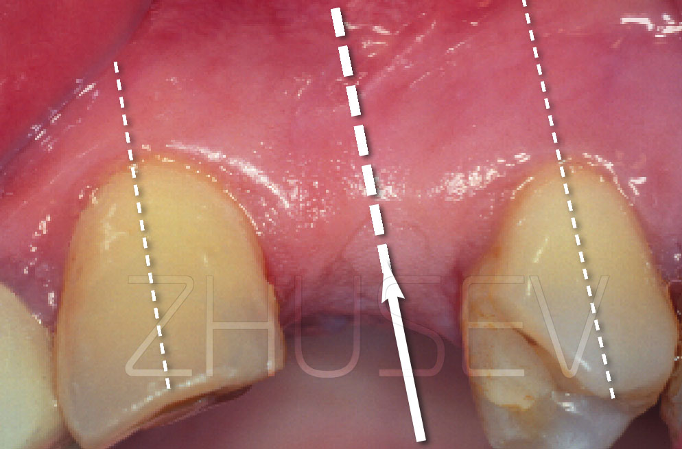
3.2-1A In the anterior part of the jaw or at the vestibular position of the implant, I strongly recommend to use esthetic healing caps. This will later enable you to fit naturally looking crowns.
3.2-1B
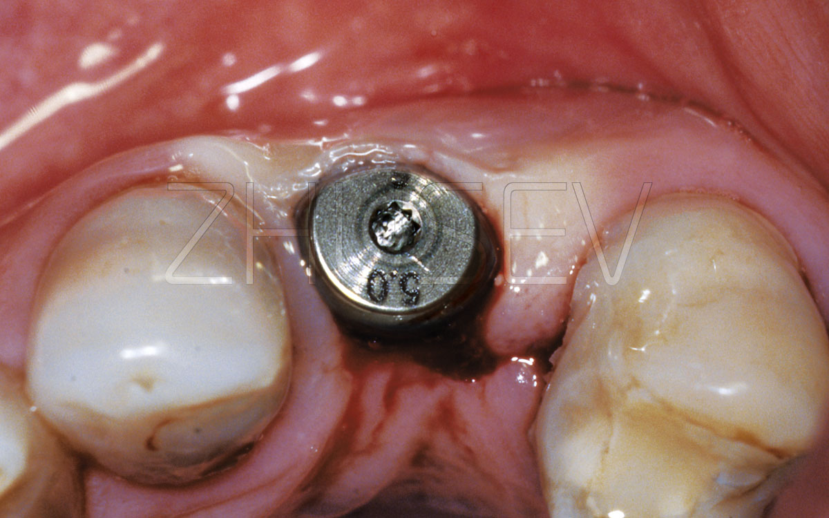
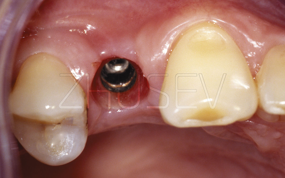
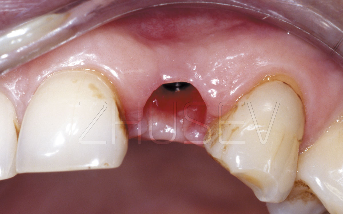
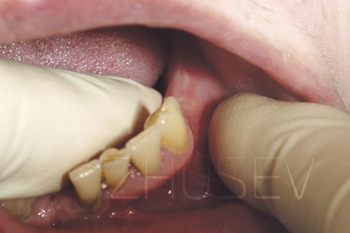
3.2-2A When the gingiva around the healing cap returns to its natural colour, we can go on to taking an impression.
3.2-2B First, we carefully wash a screwdriver slot and then put the screwdriver tight into it to avoid breaking it.
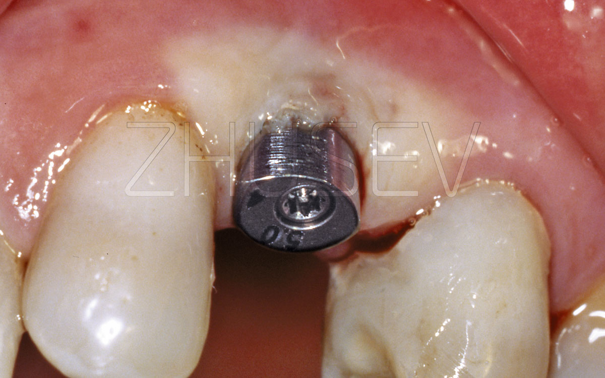
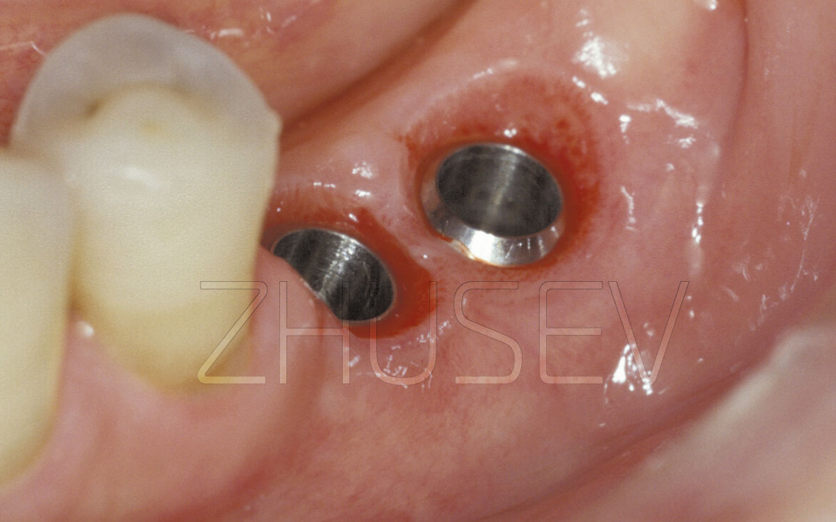
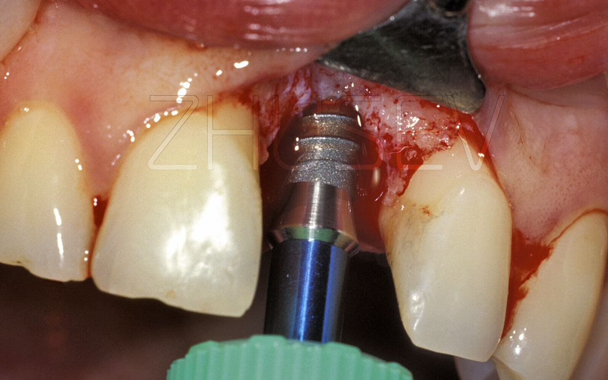
3.2-2C We remove the healing cap and clean the implant’s internal surface.
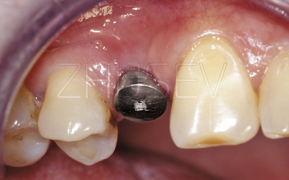
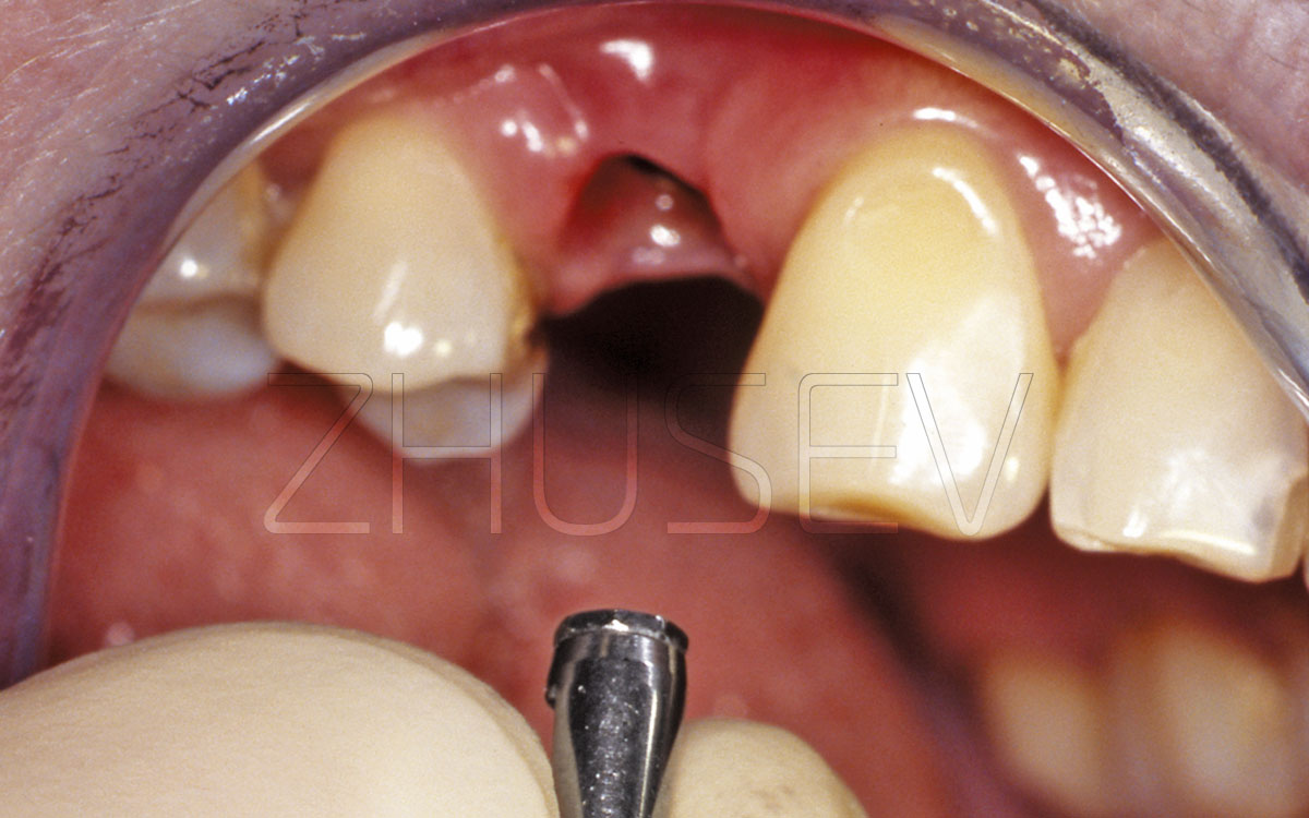
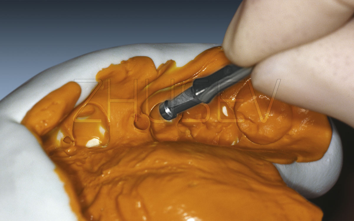
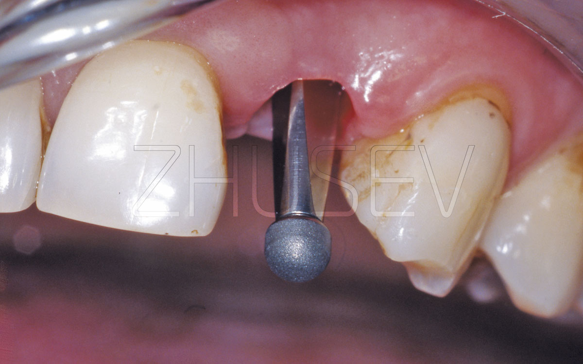
3.2-2D We turn out the impression coping’s internal screw and put its outer case into the implant, accurately fitting the polygon.
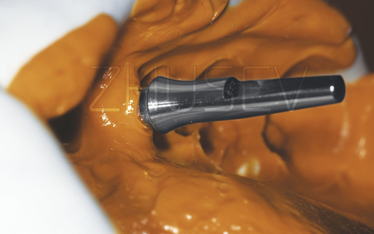
3.2-2E The impression coping installed correctly should be reliably retained in the implant.
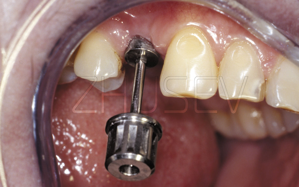
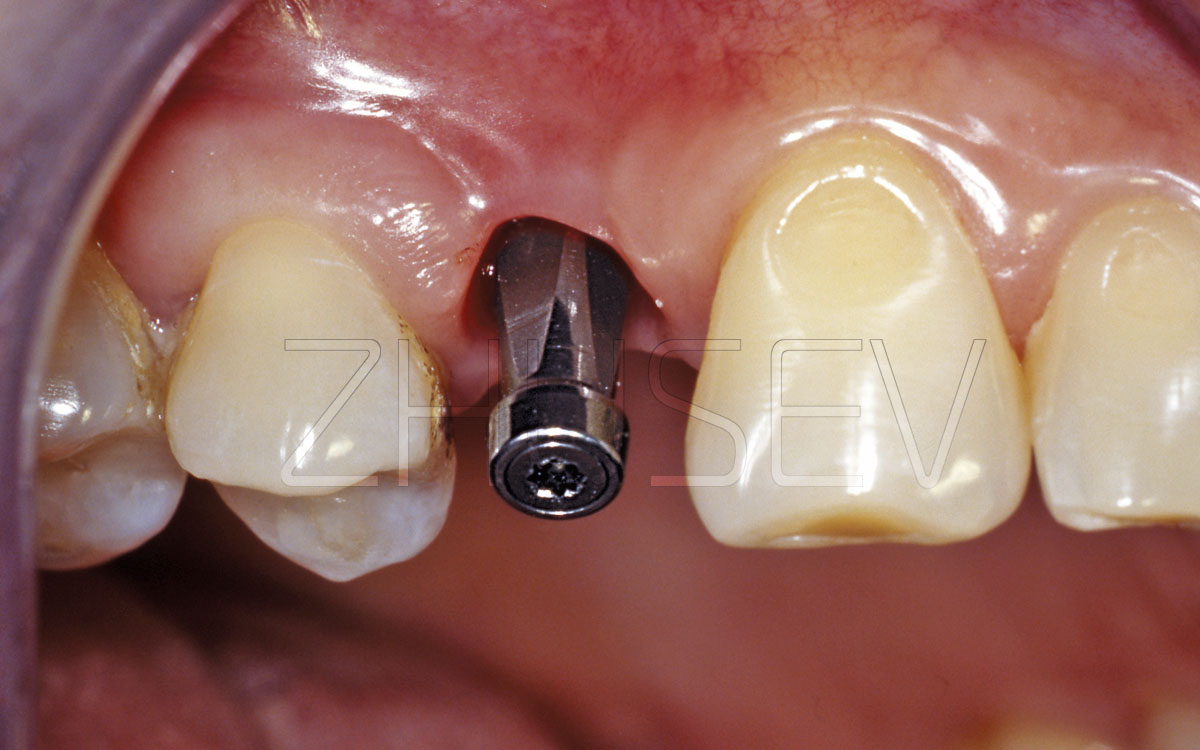
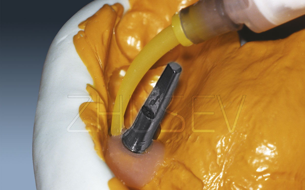
3.2-2F Turn in the internal fixing screw.
3.2-2G The impression coping is fixed. Now we take a traditional two-layer impression.
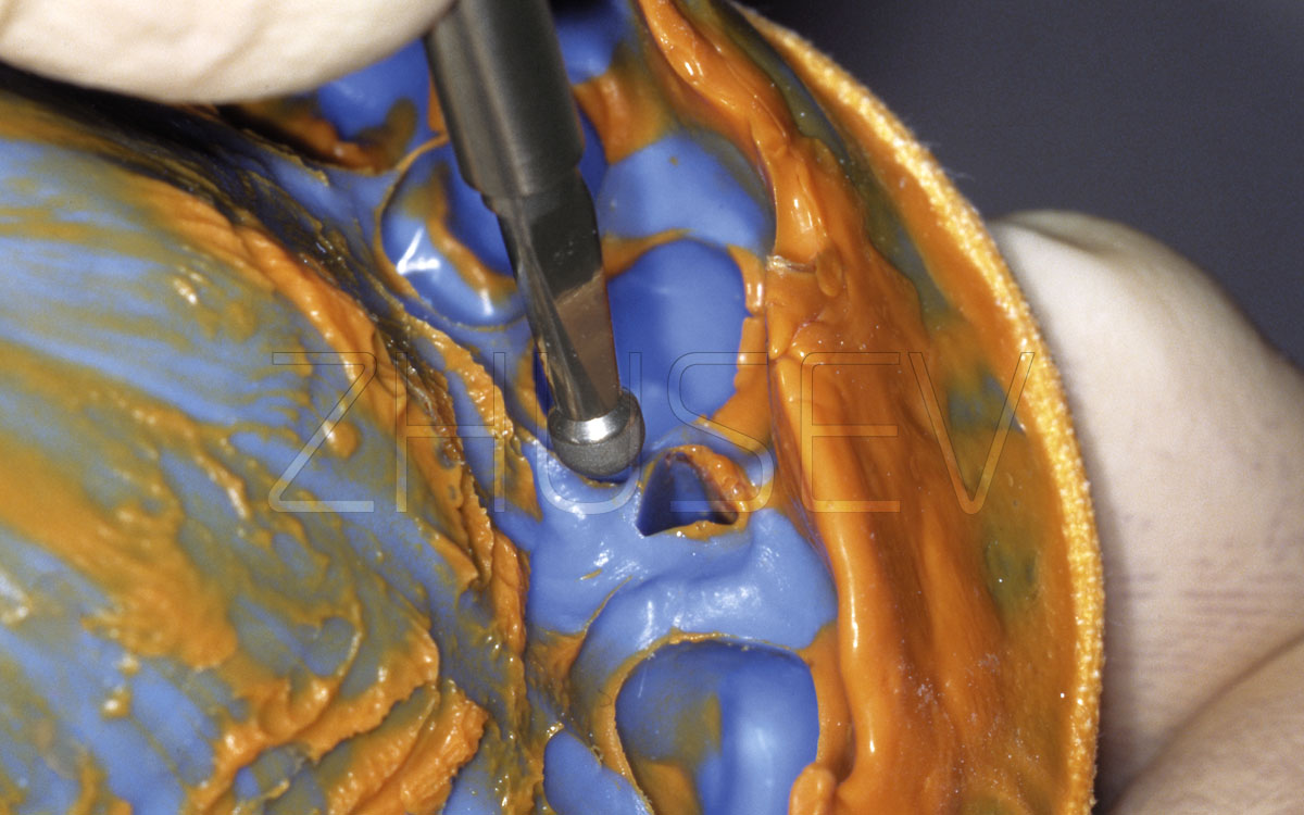
3.2-2H In a few minutes, take the impression out of the mouth. Turn the impression coping out of the implant and insert it slightly into the impression at the appropriate place. Then turn the healing cap into the implant.
3.2-2I After taking the impression, the dental technician removes the impression coping and couples it with the implant analogue.
3.2-2J At first, he fits the polygon and inserts the impression coping case tightly into the implant analogue.
3.2-2K Then check its stability and correct placement.
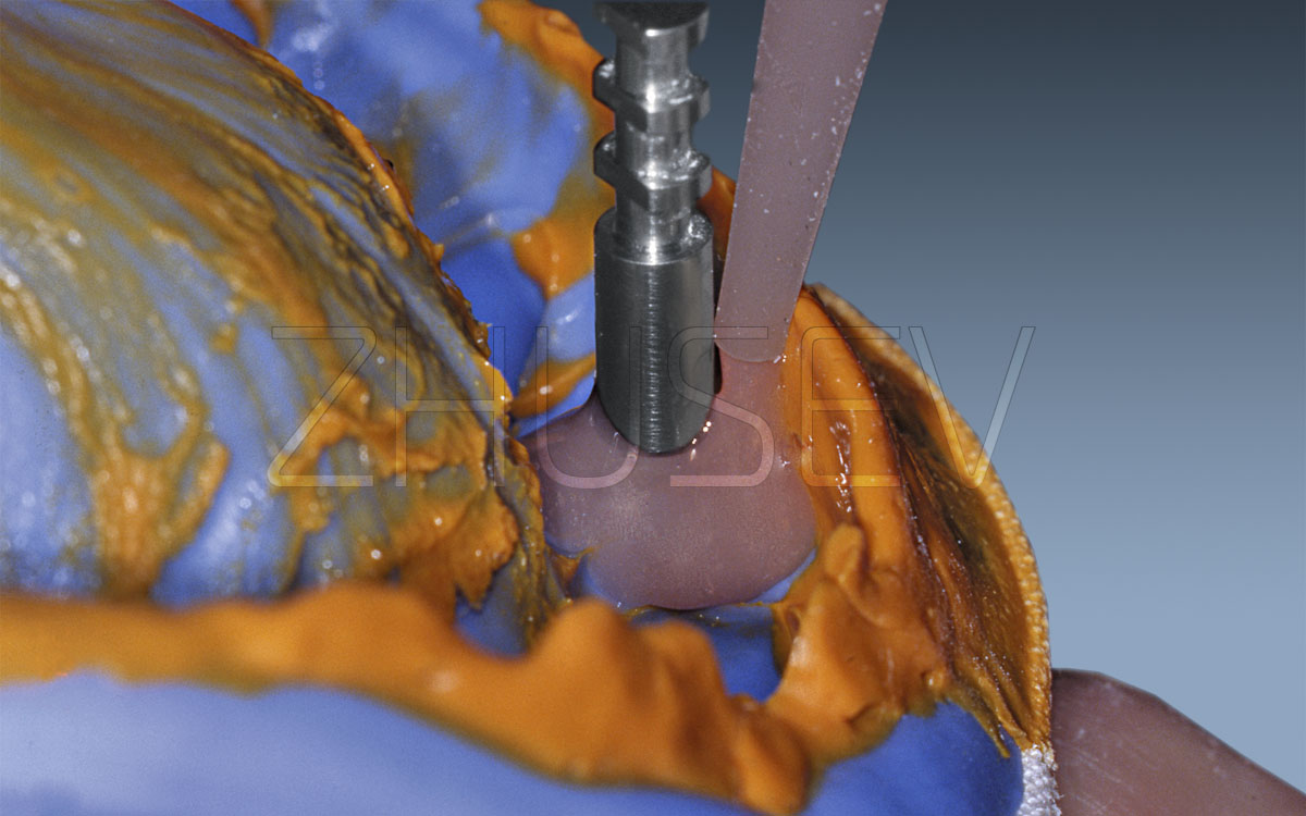
3.2-2L Only after this, tighten the internal fixing screw.
3.2-2M Accurately insert the impression coping and the implant analogue into their appropriate places in the impression.
3.2-2N Install the implant analogue and try to turn it slightly. Be sure that the impression coping’s flats coincide with corresponding places in the impression.
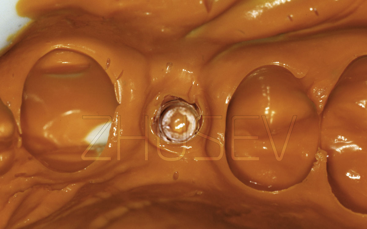
3.2-2O Put a gingival mask, which should exceed the implant’s contour height by at least 2-3 mm in all directions.
3.2-2P After the gingival mask’s hardening, we cast a basement of die stone.
3.2-2Q After the gypsum’s hardening, open the model and remove the impression coping.
3.2-2R Accurately blow through the internal surface of the implant analogue, to avoid any contamination with dust.
3.2-2S A dental technician should choose an appropriate abutment and if necessary customize it in accordance with the mucosal profile.
3.2-2T After removing the gingival mask, the dental technician should check the butt joint condition.
Then unscrew the healing cap again, attach the suprastructure chosen by the dental technician, and try on the framework. The framework should be put on the suprastructure without effort. Of course, the framework should be located in the mouth in the same way as at the master cast. If a bridge construction is supposed to be used, it should not be balancing while being fit.
If the prosthetic construction is implant-supported not with cement, but screw retention, to determine the construction fitting, a Sheffield fit test should be conducted: place the construction on the implants and tighten it with a single occlusal screw. The construction should not be balancing itself.
Unscrew the occlusal screw from the implant and screw it into the other implant — the construction also should not be balancing itself in the mouth. Do it in this way with each implant that is used in the construction.
In such cases, the framework should not squeeze or traumatize the surrounding soft tissues. When this is not the case, you should make an appropriate fitting procedure (if it is necessary, together with a framework try-on you can take a reference X-ray). Choose the colour of the prosthetic construction, take the suprastructure and the framework off, and send them to the laboratory. Insert the healing cap into the implant in the mouth.
When the prosthetic construction is fully ready, attach it with the occlusal screw or fit with cement, depending on what technique was planned. At the stage of the final fixation of the suprastructure, it is important that the requirements of cleanness and dryness (both of the suprastructure and the internal surface of the implant) should be observed, as well as the required torque values to tighten the fixing screw or the suprastructure. This should be done with a torque wrench (implant manufacturers always specify the recommended torque values).
While fitting the construction on cement, close the slot of the screw, used to attach the suprastructure to the implant with a gasket (gutta-percha one, for example). Otherwise, cement will harden in these slots and will not allow turning out the screw when it is needed.
For CONMET implants, the following torque values are recommended:
- while turning in the screw which is used to attach the abutment to the implant – 35 N/cm.
- while turning the occlusal screw into the abutment – 20 N/cm.
Remember that every time after it use, the torque wrench should be completely disassembled and sterilized.
3.2-2U Wax composition on the individually prepared abutment.
3.2-2V Checking the cap and the abutment on the model. The cast cap is checked on the abutment.
3.2-2W After the check, we can do the final try-on in the mouth. Note that the dental technician marked the facial side of the abutment with a colour marking.
3.2-2X Before fixing the crown on cement, close the internal screw which attaches the abutment to the implant, with a gasket.
3.2-2Y An ideal fit of the cap. There is no change of surrounding mucosa colour, or gingival bleeding.
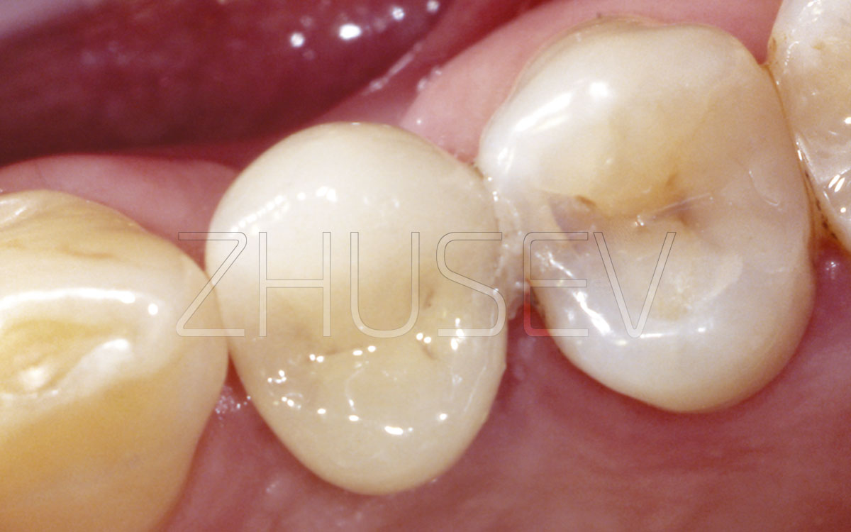
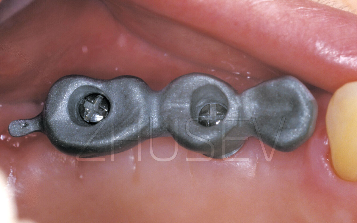
3.2-2Z View of the occlusal surface of the fixed crown.
3.2-2AA The finished view. The optimum fitting of gingival tissue.
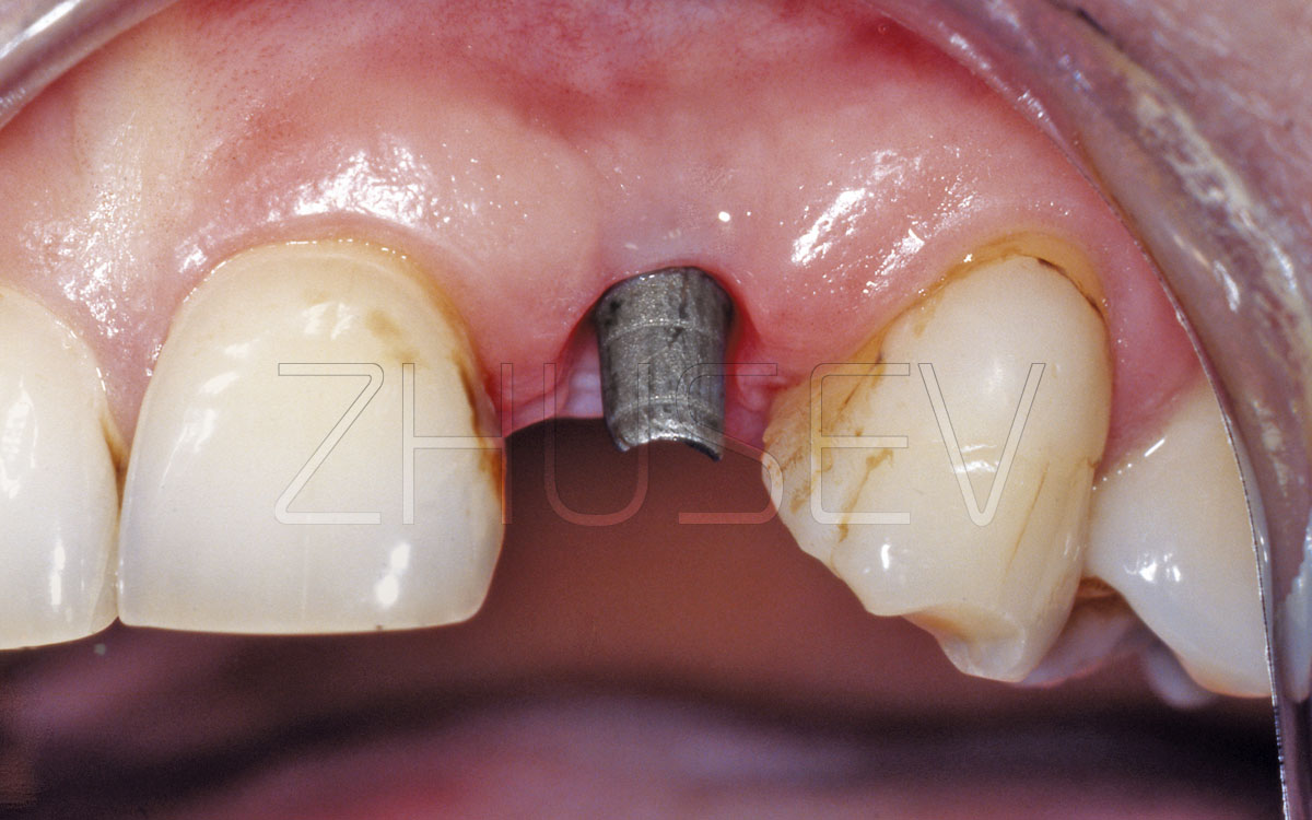
3.2-3A Tighten the healing cap, but do not apply excessive force while doing this.
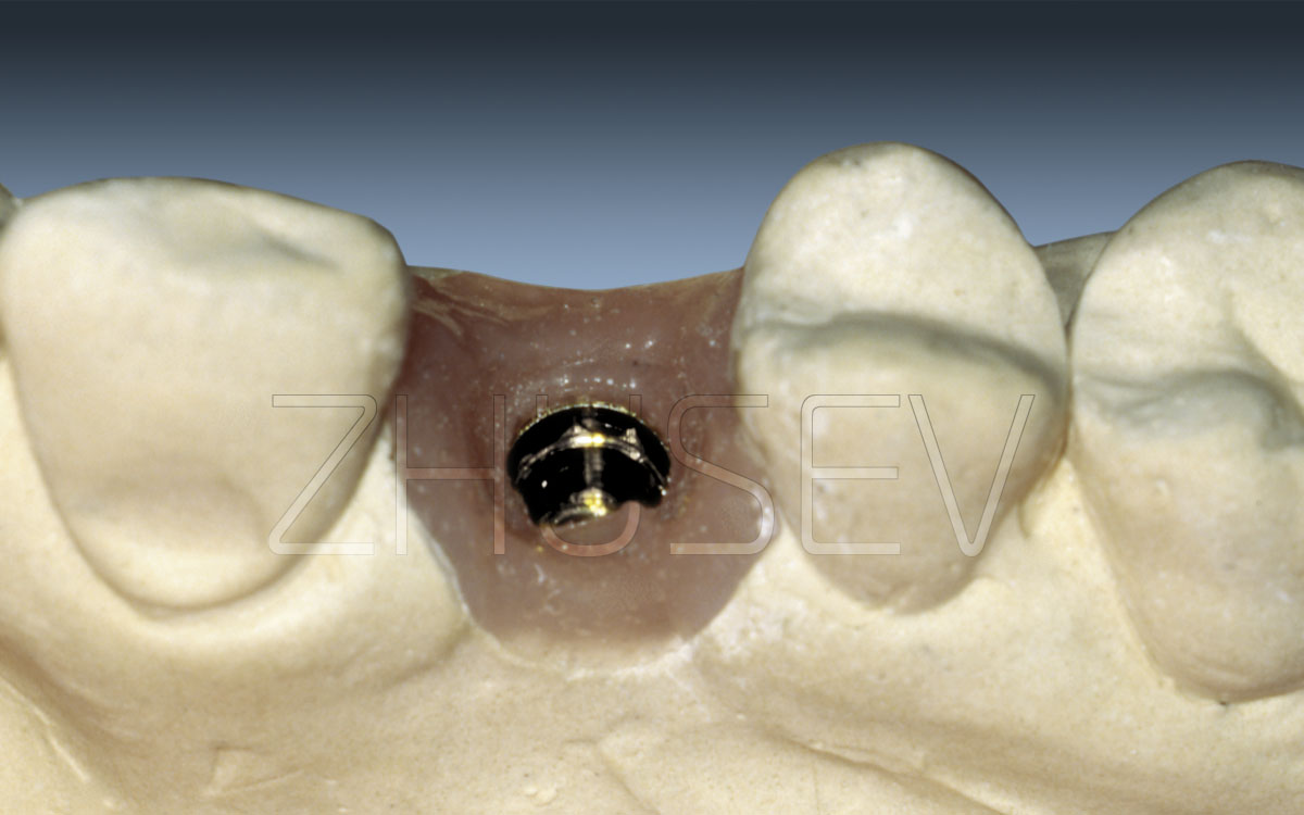
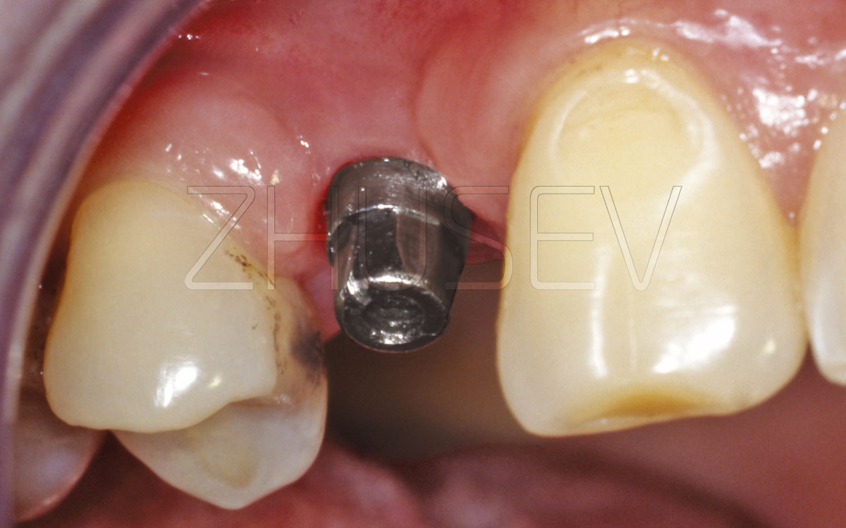
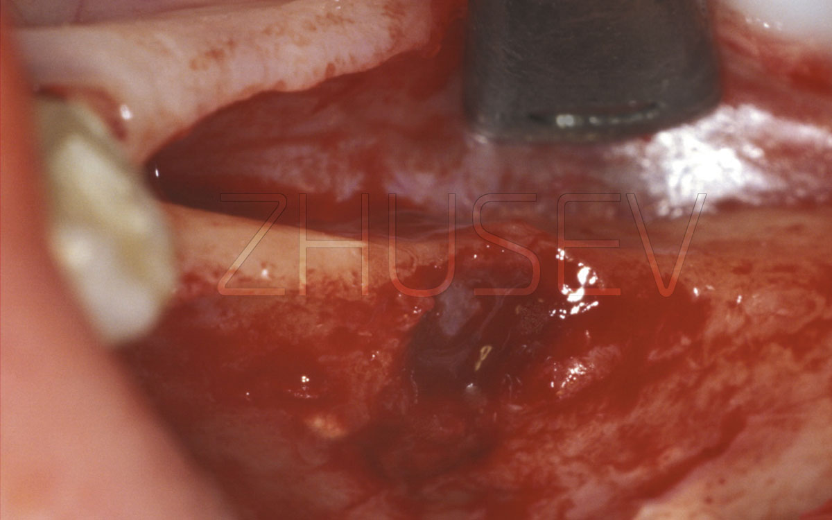
3.2-3B Turn out the healing cap and make sure that in the contact areas the mucosa’s colour is usual and they do not bleed, and the implant internal surface is clean.
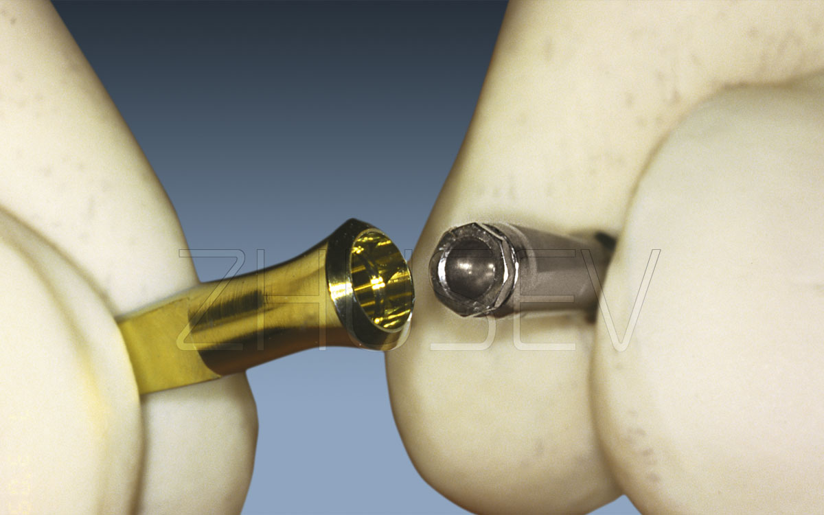
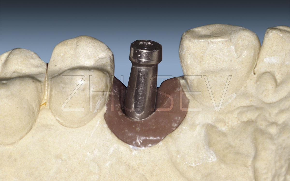
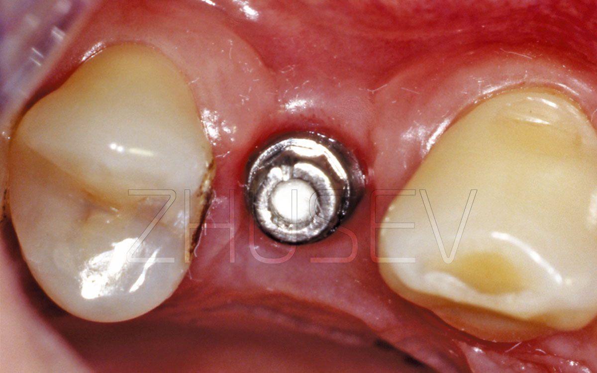
3.2-3C While you are installing an impression coping, first install the outer case into the implant’s hexagon, and then turn in the fixing screw.
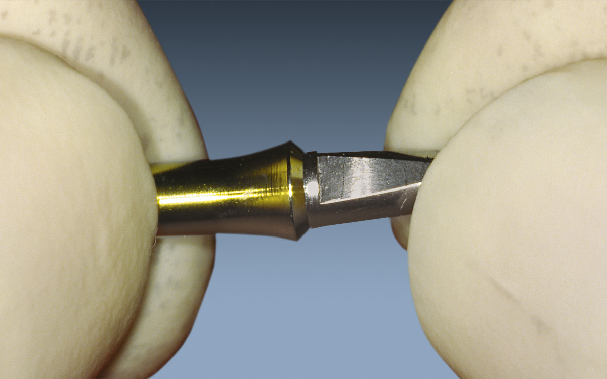
3.2-3D Turn in the fixing screw by hand only! Don’t use nippers or haemostatic forceps to tighten it!
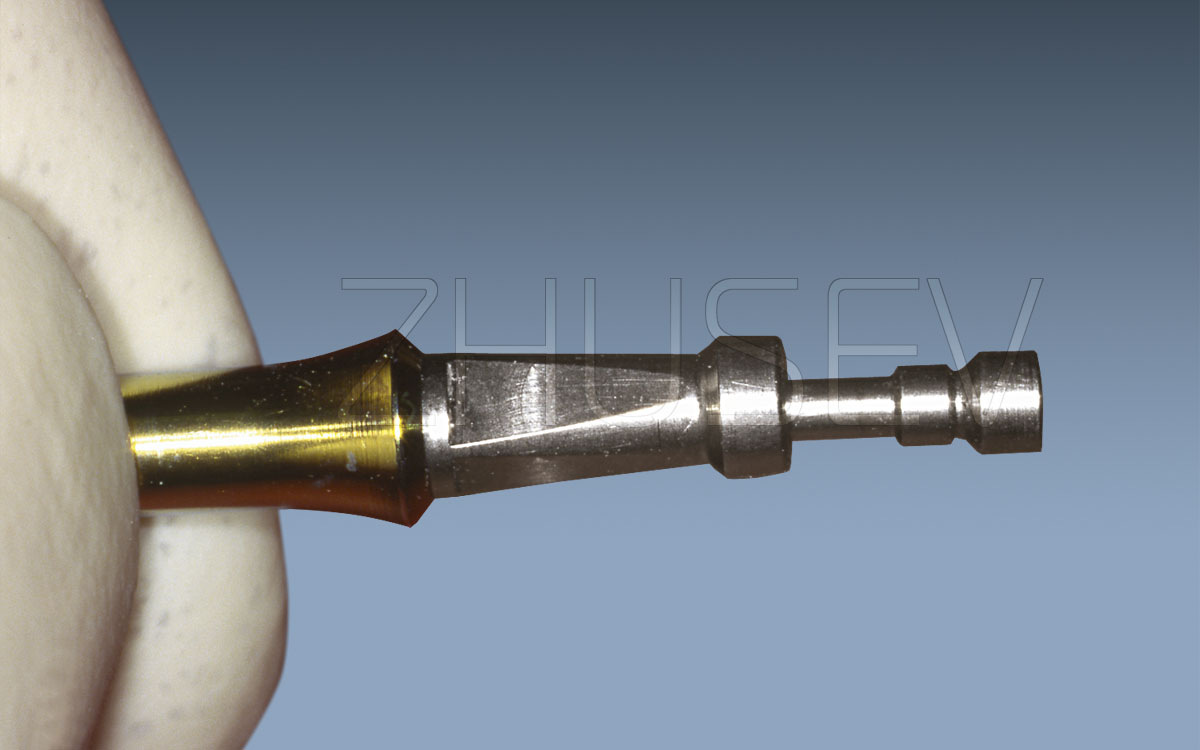
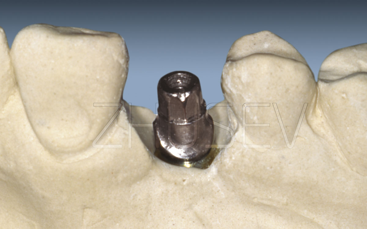
3.2-3E After taking the impression, turn the impression coping out of the implant and turn it into a transfer pin. First, fit the interior faces, and only then tighten it with the fixing screw.
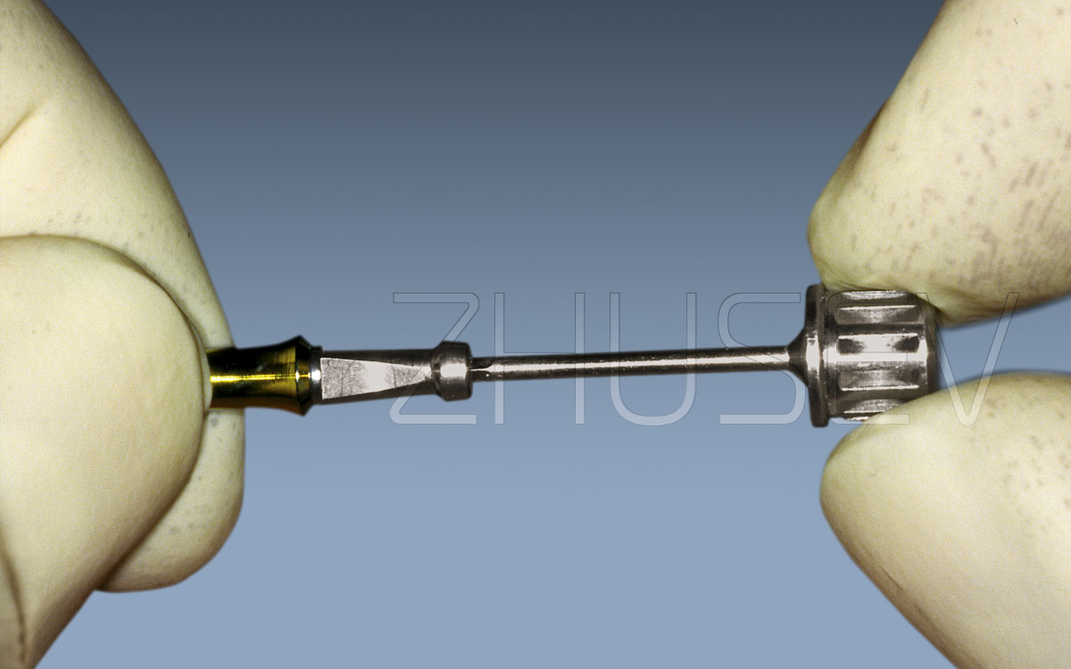
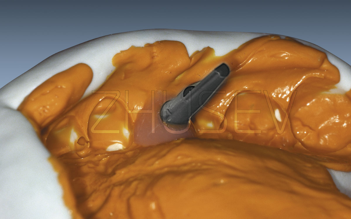
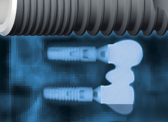
3.2-3F When you apply a trifacial closed tray impression coping, the impression is always distinct. Fitting the impression causes no problems.
3.2-3G Process the impression with silicon insulating material and put a gingival mask around the impression coping. Then cast a model of die stone.
3.2-3H After hardening of the die stone, open the model, turn out the impression coping, and select the appropriate abutment.
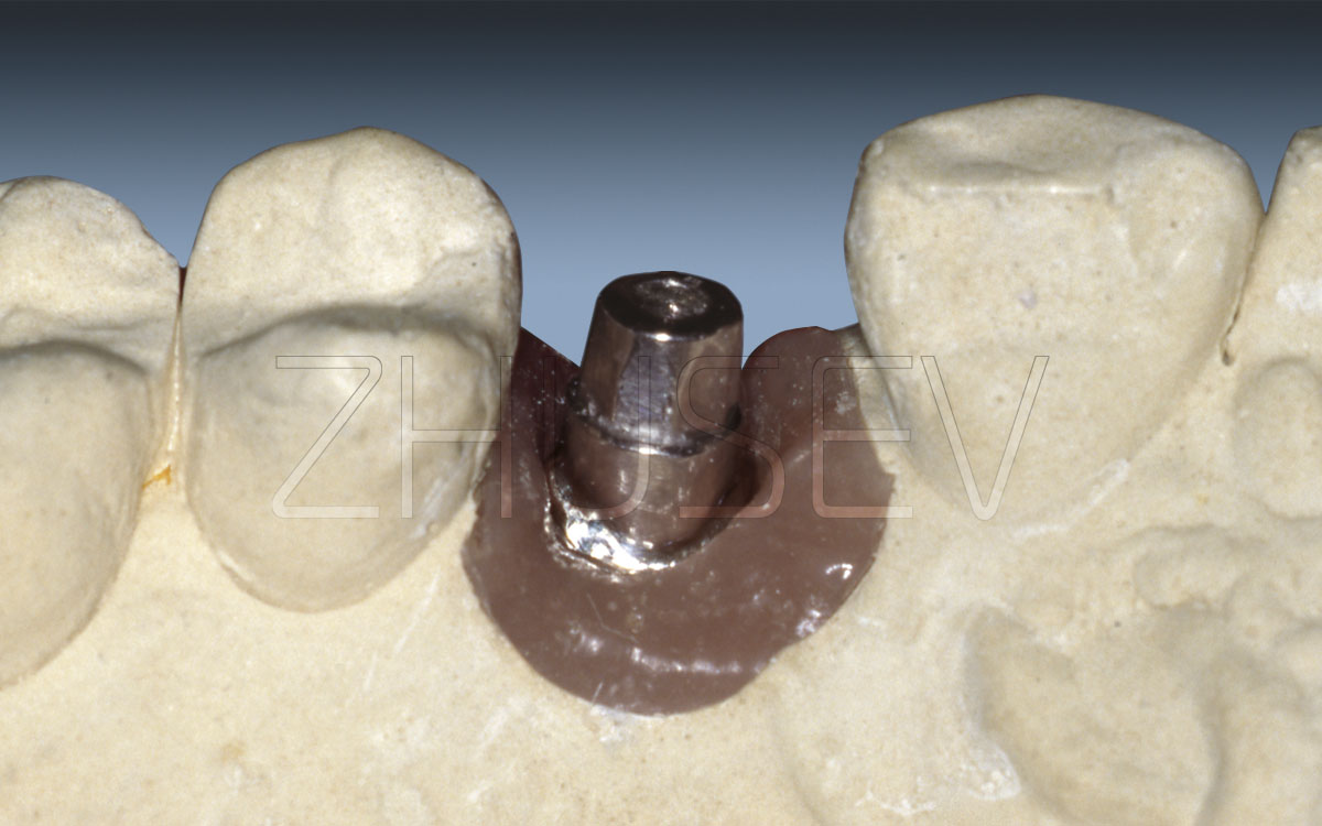
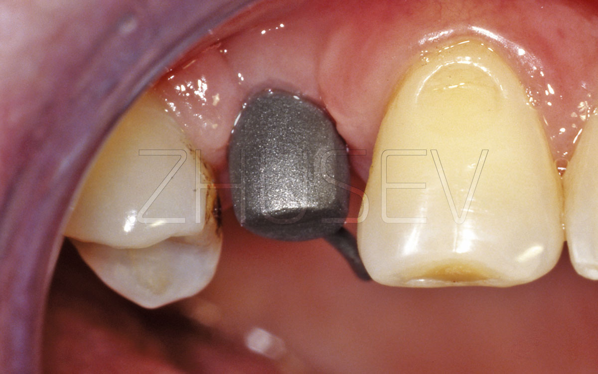
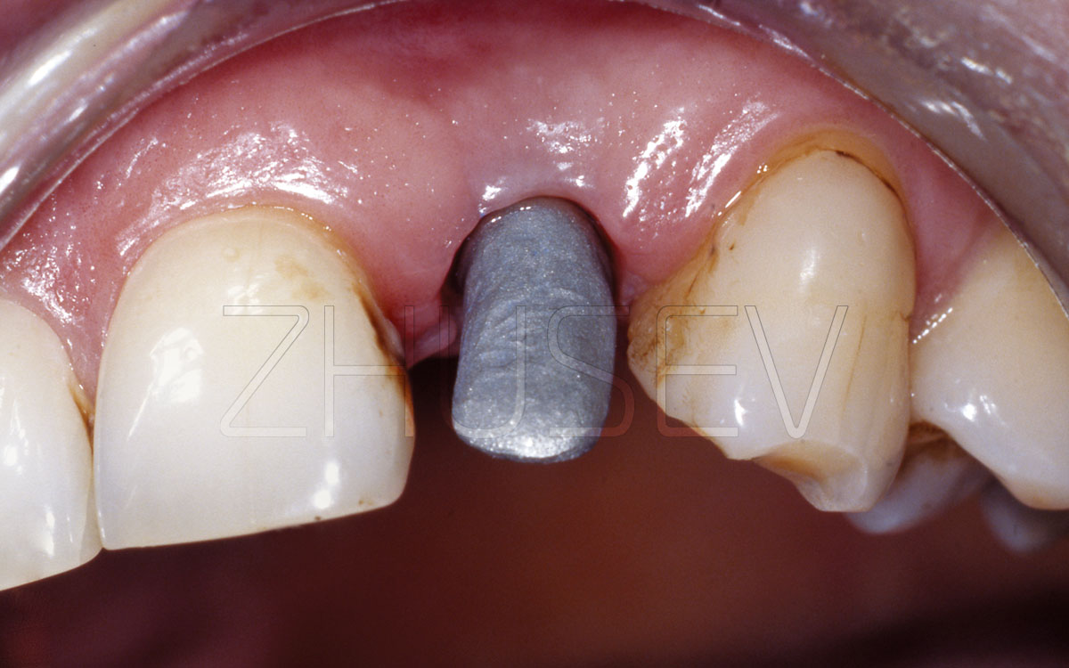
3.2-3I View of a standard straight abutment in the mouth after slight individual preparation.
3.2-3J Check the marginal fit of the cap in the mouth. Pressing on the cap should not cause the change in the colour of the soft tissues around the implant.
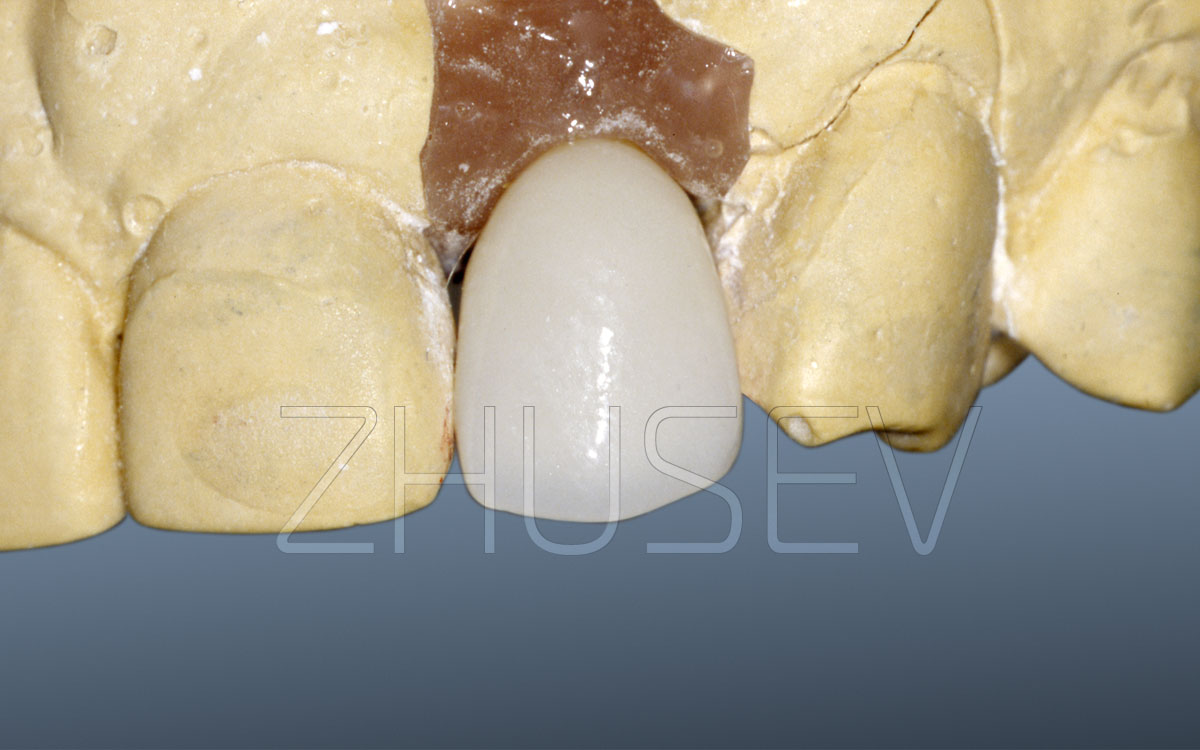
3.2-3K A porcelain-faced cap, placed on the gypsum master cast.
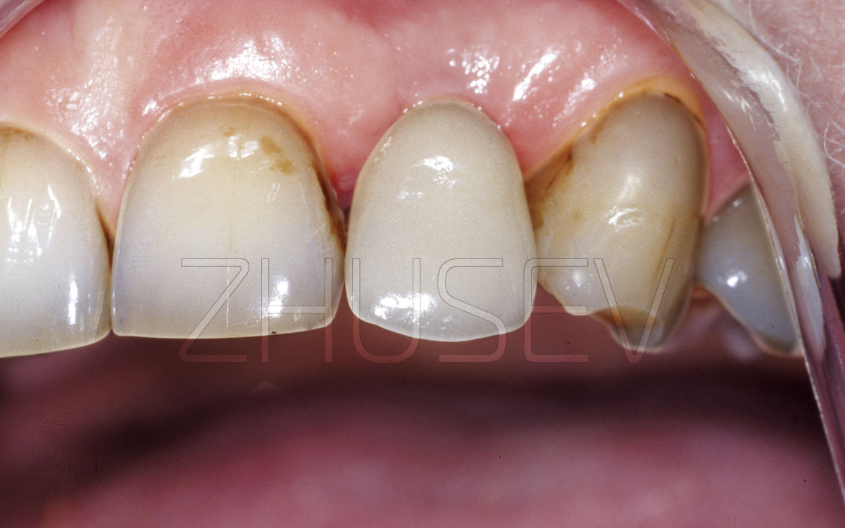
3.2-3L The finished work. The normal state of the soft tissues and interdental papillae in the proximity of the implant.